Model 1.

![]() between the disks. This is a “2D” case – electric field lies in the plane of the disks. You may think of these disks as cross-sections of very long charged cylinders (due to translational symmetry electric field lies in the plane perpendicular to the axes of the cylinders). Our goal is to find electric field
between the disks. This is a “2D” case – electric field lies in the plane of the disks. You may think of these disks as cross-sections of very long charged cylinders (due to translational symmetry electric field lies in the plane perpendicular to the axes of the cylinders). Our goal is to find electric field ![]() and potential
and potential ![]() along the line connecting the centers of the disks.
along the line connecting the centers of the disks.
- Recall that in “2D” case (I.6) the magnitude of the electric field due to charged disk is inversely proportional to the distance from its center:
 .
. - Let us determine the value of the constant
 . Assume the disks have radii
  and their centers lie on
  axis at points
  and
and  . Consider electric field at some point on the
  axis between the circles(see Figure M.1). We assume the “upper” circle is at potential
  while the “lower” circle is at 0 potential (connected to GND). Electric field at point
  due to “upper” positively charged disk is
 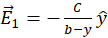 . Electric field at point
  due to “lower” negatively charged disk is
 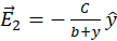 . Electric fields
  and
and  have the same direction therefore the net field at point
  is:
is:
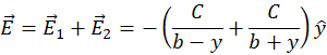
(M.1)
The difference in electric potential between the disks:

(M.2)
Integrate (M.2) and express
 in terms of
  ,
,  ,
,  . Remember,
  is a known quantity.
 - Now we will derive the expression for the potential
 on the line connecting disks (
 -axis in Figure M.1). We know that the potential of the lower disk is 0. We will integrate electric field (M.1) from the lower disk to the point
  :
:
Figure M.2 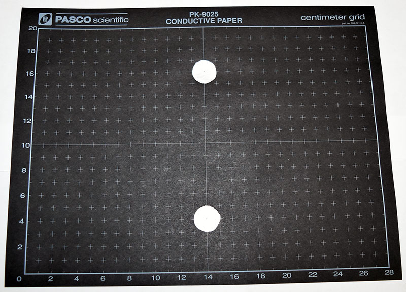

or
(M.3)
You already expressed
 in terms of
  ,
,  ,
,  in part 2. Integrate (M.3) and express
  in terms of
  ,
,  ,
,  and, of course,
  .
.
What to submit in Prelab:
1. ![]() in terms of
in terms of ![]() ,
, ![]() ,
, ![]() (with short derivation)
(with short derivation)
2. ![]() in terms of
in terms of ![]() ,
, ![]() ,
, ![]() ,
, ![]() (with short derivation)
(with short derivation)
Model 2.
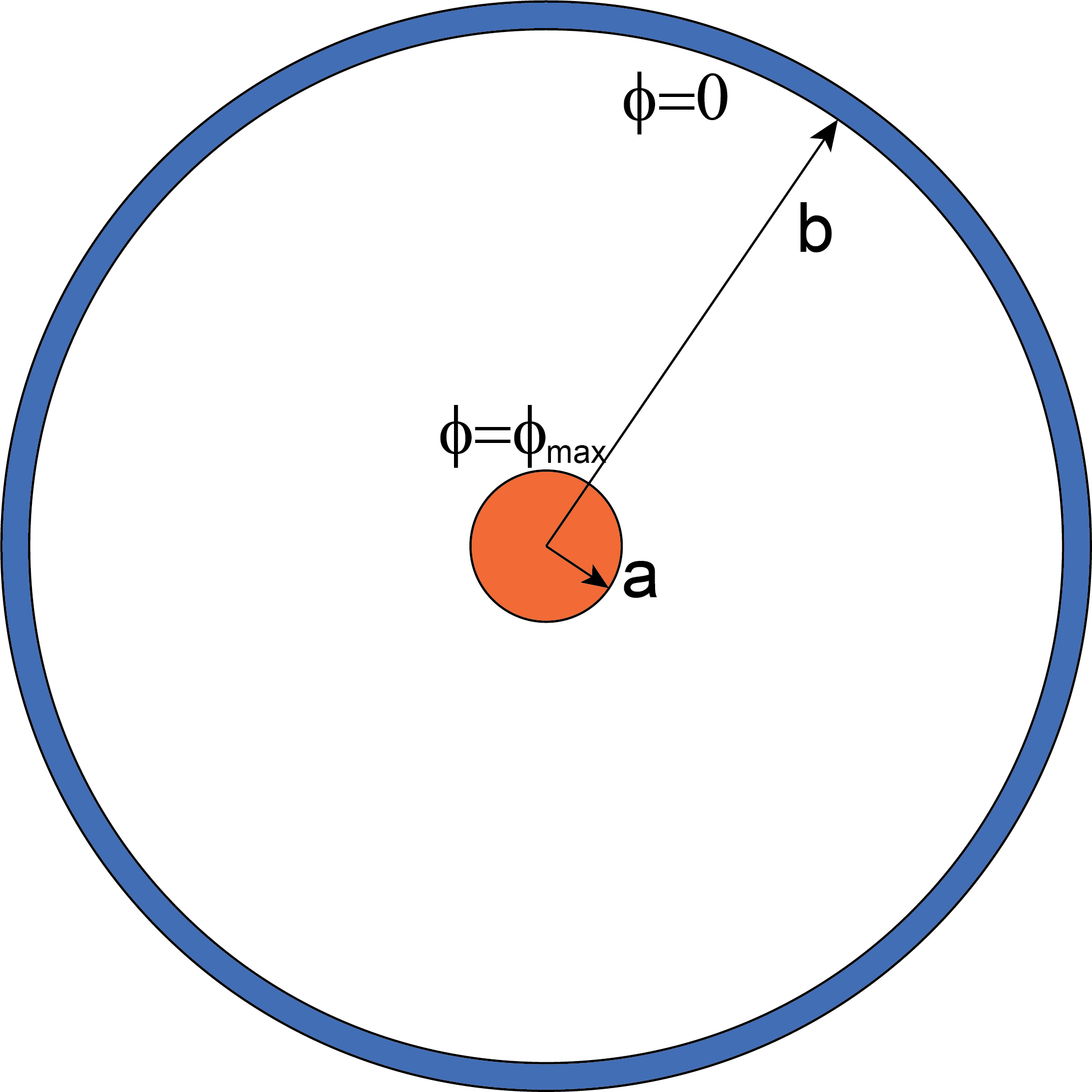
Now we will derive expression for the electric potential between two concentric circles with known potential difference. A small conducting disk of radius ![]() at potential
at potential ![]() is concentric with a larger circle with inner radius
is concentric with a larger circle with inner radius ![]() at potential
at potential ![]() (see Figure M.3). Our goal is to find expressions for
(see Figure M.3). Our goal is to find expressions for ![]() and
and ![]() where
where ![]() is the distance to the center of the circles.
is the distance to the center of the circles.
- Electric field in this setup is directed radially outward and, due to circular symmetry, is inversely proportional to the distance from the center:

- We need to find coefficient
 and express it in terms of
  ,
,  , and
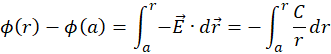
, and  . Express the difference in electric potential between the circles through the line integral of electric field along radial line:
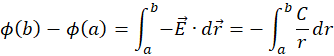
(M.4)
Integrate (M.4) and use
 and
and 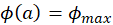 to express coefficient
  in terms of
  ,
,  , and
, and  .
. - Potential
 at distance
  from the center:
(M.5)
You already expressed
 in terms of
  ,
,  ,
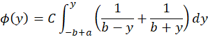
,  in part 2. Integrate (M.5) and express
  in terms of
  ,
,  ,
,  and, of course,
  .
.
Note: an alternative approach of obtaining the expression for the potential ![]() is solving the Laplace's equation in cylindrical coordinates
is solving the Laplace's equation in cylindrical coordinates ![]() with boundary condition
with boundary condition ![]() and
and ![]() .
.
What to submit in Prelab:
1. ![]() in terms of
in terms of ![]() ,
, ![]() ,
, ![]() (with a very short derivation)
(with a very short derivation)
2. ![]() in terms of
in terms of ![]() ,
, ![]() ,
, ![]() ,
, ![]() (with short derivation)
(with short derivation)