Experiment 1. Measuring Capacitance.
You have a set of 4 capacitors and 4 resistors. Your goal in this experiment is to measure the capacitances of given capacitors. The values written on capacitors are not accurate since the tolerance is quite large (20%). In this Experiment you will obtain (relatively) accurate values for capacitances that you will use in further calculations in this lab.
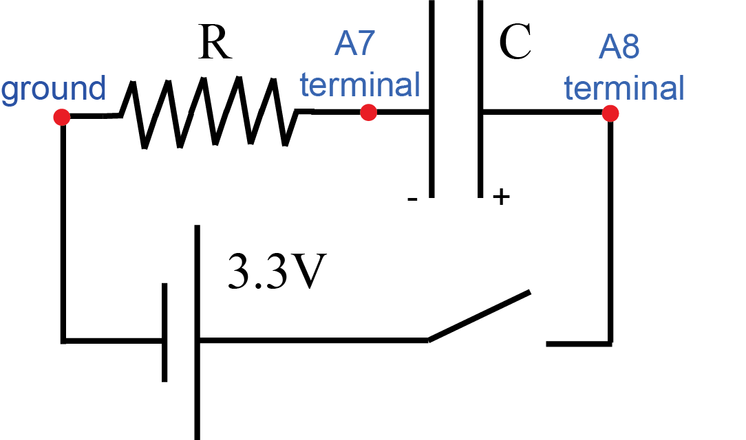
- Build the basic RC circuit shown in the diagram in Figure E.1 – resistor and capacitor in series. We will study RC circuits in more detail later in class and in the following lab. As you connect the power (voltage) supply across RC combination the charge starts to build up on the (initially uncharged) capacitor. This charge flows through the resistor. The amount of charge flowing to the capacitor per unit time is the current in the resistor. iOLab device cannot measure the current directly but we can measure the voltage across the resistor and use Ohm’s Law (I.2) to calculate the current. Once you know the current as a function of time you may integrate it with respect to time and obtain the total charge accumulated on the capacitor.
- Make sure the capacitor has zero charge at the beginning of your experiment by short-circuiting it (touch both terminals of the capacitor with a conducting wire - and make sure the A8 probe reads zero).
- Connect the terminal strip with A8 terminal to the D6 voltage source in the iOLab device. Turn on the voltage. Initial current (and thus voltage across the resistor registered by A7 probe) is relatively high. If fact, the initial voltage across the resistor should equal that of the voltage source since the capacitor initially has zero charge and thus zero voltage. As the charge accumulates on the capacitor the voltage across it grows and the resulting electric field resists further charge increase. This leads to the decrease in the rate of further charge buildup on the capacitor (i.e. current) and thus the decrease in the voltage across the resistor. Since the resistor and the capacitor are connected in series, the sum of voltages across them at any time equals to the net voltage of the source (3.3V). Therefore, as the voltage across the capacitor increases with time, the voltage across the resistor decays. Wait until voltage across the resistor drops to near zero (a few mV). At that time the voltage across the capacitor equals to that of the voltage source (3.3V).
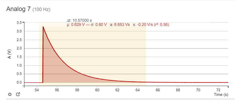
- You may now integrate (i.e. find the area under the curve) the voltage across the resistor with respect to time and divide the obtained value by the resistance. This yields the integral of the current with respect to time, i.e. the total charge that passed through the resistor. The integration of the voltage data is easily performed in the iOLab software with the help of “Statistics” tool (see Figure E.2). Zoom in on the area of interest, click on Statistics button and select the area you want to integrate.
- Once you know the net charge accumulated on the capacitor and the final voltage across it (i.e. the voltage of the source) you may calculate its capacitance.
- Repeat experiment with each capacitor 5 times, record your data in Excel and calculate the mean and standard deviation for your capacitance measurements.
- Suggested combinations of resistors and capacitors are shown in Table E.1. You may use any combinations of Rs and Cs but choosing them so that their product RC (which has the dimension of time) is of the order of (few) seconds will ensure that the wait time for the current to vanish is reasonable.
- Your report for this experiment should contain your results for capacitance measurements (mean and standard deviations) for the four given capacitors. Make the table similar to Table E.2 and include it to your report.
C, µF (Stated value) |
R, kΩ |
|---|---|
47 |
47 |
100 |
22 |
470 |
4.7 |
1000 |
2.2 |
Stated value, µF Measured value, µF 47 100 470 1000
![]()
Experiment 2. Energy Stored in the Capacitor.
In this experiment we will discharge a fully charged capacitor through the resistor and compare the initial energy stored in the capacitor with the amount of heat dissipated in the resistor.
This experiment uses the same initial setup (basic RC circuit) as the Experiment 1 – refer to Figure E.1 for initial circuit diagram. You only need to do this experiment for one set of Capacitor/Resistor (at your discretion, for example 470µF and 4.7kΩ).
- Fully charge the capacitor (i.e. wait until voltage across resistor vanishes).
- Physically disconnect the wire from the voltage source.
- Observe that voltage across the capacitor (A8 probe) remains unchanged at about 3.3V. This means the capacitor holds the charge.
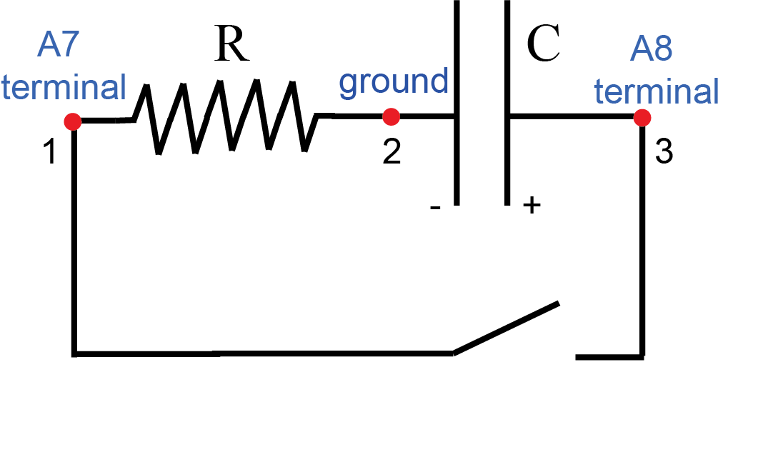
- Carefully switch ground and A7 probes (see Figure E.3) so that ground probe is connected to the terminal strip shared by the resistor and the capacitor (point 2 on the diagram), and A7 probe is connected to the terminal strip previously occupied by the ground (point 1). We do this because the iOLab device can only measure voltages in the range between 0 and 3.3V. It cannot measure negative voltages. As we discharge the capacitor current flows from the positive (right) plate of the capacitor to the negative one – i.e. clockwise in the diagram in Figure E.3. Thus point 1 would be at higher potential than point 2. If we do not switch A7 and ground the A7 probe would only register constant 0 since it cannot show negative (relative to the ground) voltage.
- Click record button and connect points 1 and 3 with the jumper wire.
- Observe the voltage across the resistor vs. time on A7 probe signal. (Since points 1 and 3 are connected by jumper wire potentials at points 1 and 3 are the same. Therefore, signals A7 and A8 should be identical). Wait until current in the circuit vanishes.
- The power (the rate of heat generation in the resistor) is
 (I.5). To obtain the net amount of energy dissipated in the resistor we need to integrate
  with respect to time. We cannot do that in iOLab software so we will perform the integration in Excel. Upload A7 data to the cloud and download it from there in CSV format. Open CSV file in Excel.
 - You may remove cells with data preceding the capacitor discharge.
- Create an additional column that contains the energy dissipated over small time interval:
 (here
(here  is the time interval between consecutive data points).
 - Sum all
 . This is the net energy dissipated in the resistor during capacitor’s discharge.
 - Calculate initial energy stored on the fully charged capacitor (I.13). Compare it with the energy dissipated in the resistor. Your report should contain these energy values. Are these energies close? Which one is larger? What might be the reason for the discrepancy? Answer these questions in your report.
Experiment 3. Adding a Capacitor.
In this experiment we will charge a capacitor and then disconnect the battery and connect another (uncharged) capacitor in parallel. We will measure the amount of charge transferred between the capacitors, new voltage established across the combination, and the energy lost during this process. This experiment follows Exercise 3.66 from your homework assignment.
This experiment uses the same initial setup (basic RC circuit) as the Experiment 1 – refer to Figure E.1 for initial circuit diagram. You will only do this experiment for one set of Capacitor/Resistor: 1000µF and 2.2kΩ.
- Fully charge capacitor (i.e. wait until voltage across the resistor vanishes).
- Disconnect the voltage source (terminal D6).
- Observe that voltage across the capacitor (A8 probe) remains unchanged at about 3.3V. This means the capacitor holds the charge.
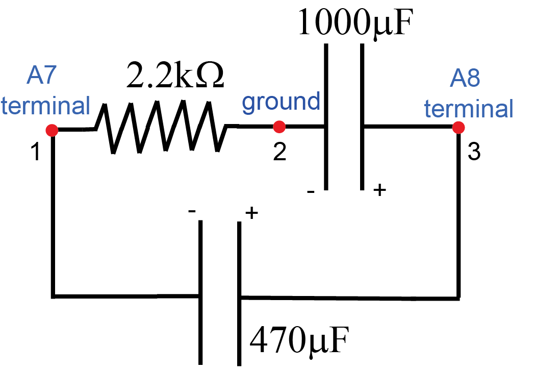
- Carefully switch ground and A7 probes (see Figure E.4) so that ground probe is connected to the terminal strip shared by the resistor and the capacitor (point 2 on the diagram), and A7 probe is connected to the terminal strip previously occupied by the ground (point 1). I explained the need for such switch in the previous experiment.
- Connect uncharged 470µF capacitor across the combination – i.e. between points 1 and 3 in the diagram in Figure E.4.
- Voltage registered by A8 terminal will stabilize at the new value
 (lower than initial value of
  ) This is a new voltage across the combination. Record this value and show it in your report.
 - A7 terminal records voltage (and hence current) across 2.2kΩ resistor. This current results from redistribution of charge from 1000µF to 470µF capacitor. Wait until this current vanishes. Integrate the current in 2.2kΩ resistor and obtain the total charge
 transferred from 1000µF capacitor to 470µF capacitor. Save the screenshot of the A7 signal with the value of the integral shown (similar to Figure E.2). Include it in your report.
 - Calculate energy
 stored initially at 1000µF capacitor (at voltage
  ) - see (I.13).
 - Calculate energy stored at the combination of 1000µF and 470µF in parallel
 (at measured voltage
  ). Use accurate (measured in Experiment 1) values for capacitances rather than stated values in your calculations.
 - Calculate the change in energy stored at the capacitors
 .
. - Calculate the heat generated in the resistor. Follow the same algorithm as in the previous experiment – export data for the voltage across the 2.2kΩ resistor to Excel and integrate the power
 with respect to time. Compare the net amount of heat dissipated in the resistor with the change in energy stored at the capacitors
  . Are they the same? If not, which one is larger and what might be the reason for the discrepancy? Answer these questions in your report.
 - Now we will do theoretical calculations and compare them with measured values. Assume you have capacitor
 at voltage
  . At certain time external voltage source is disconnected and the uncharged capacitor
  is connected in parallel to
  .
.
- Draw corresponding circuit diagram.
- Derive the expression for the new voltage across the combination (
 in terms of
  ,
,  and
and  ).
). - Derive the expression for the charge transferred from
 to
to  . (
. ( in terms of
  ,
,  and
and  ). (Hint: use charge conservation – i.e. the net charge on the combination of
  and
and  is the same as the initial charge on
  ).
). - Derive the expression for the change in energy stored at the capacitors (
 in terms of
  ,
,  and
and  )
) - Plug in
 and accurate values for capacitances
  and
and  in the expressions you derived in b), c), and d). Compare with your measured values.
- Your report should have the screenshot of your A7 signal in this experiment (voltage across 2.2kΩ resistor, with the value of the integral shown – like Figure E.2) and your calculation of the measured value of
 based on this integral. Also include the measured value of
  and the heat generated in the resistor. Include your comments/answers for part 11). Include derivations and expressions for theoretical values of
  and
and  and
and  from part 12). How well do your theoretical estimates match measured values?
Experiment 4. Capacitors in Parallel.
In this experiment we will measure equivalent capacitance of two capacitors connected in parallel and compare it with the calculated value.
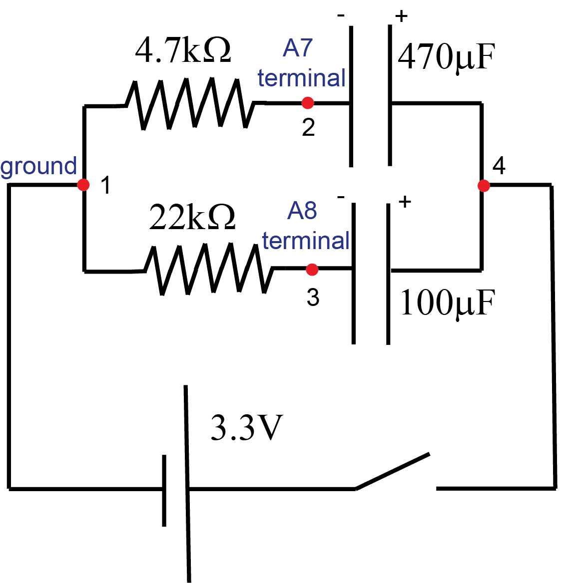
- Build the circuit shown in the diagram in Figure E.5. Please pay attention to the polarity of the capacitors.
- Make sure both capacitors are initially uncharged by short-circuiting them (touch points 1 and 4 with a jumper wire and wait a few seconds).
- Connect the D6 voltage source in the iOLab device to the point 4 on the diagram. Turn on the voltage. Wait until both capacitors are fully charged.
- Calculate the charge on each capacitor (integrate the current through appropriate resistors as in Experiment 1) and calculate the total charge on the combination:
 .
. - The voltage across the combination of these capacitors is 3.3V. Calculate the equivalent capacitance
 of this combination using
  and the voltage across the combination.
 - Your report should contain your value for
 , calculated value for
  , and comparison with the predicted value for the equivalent capacitance of two capacitors in parallel (I.7). Please note that I have indicated the stated values of the capacitances on my diagram. In your calculation use accurate values for capacitances you obtained in Experiment 1.
Experiment 5. Reversing Polarity.
In this experiment we will investigate the redistribution of charges on two parallel capacitors when the polarity of one of them is reversed. This experiment uses the same initial setup (with one small modification) as the Experiment 4. I will refer to the diagram from the previous experiment in Figure E.5.
- Build the circuit shown in the diagram Figure E.5 (or just use the setup you still have on your breadboard from your previous experiment). There is one difference from the Experiment 4 setup: 100µF capacitor should have its positive terminal connected to the resistor and negative terminal to point 4.
- In this Experiment we will use another voltage source from the iOLab device – DAC. Connect the “DAC" voltage source in the iOLab device to the point 4 on the diagram. On the DAC Output menu select 1.8V voltage. Click record button. Turn on the voltage. Wait until both capacitors are fully charged.
- Physically disconnect (remove) the wire from the voltage source. Move A7 terminal wire from point 2 to point 4. A7 voltage should indicate voltage close to 1.8V. It now measures the voltage across the combination of two capacitors in parallel.
- Carefully remove 100µF capacitor, invert its polarity (i.e. switch positive and negative terminals) and insert it back in the circuit.
- Voltage across the whole combination registered by A7 terminal will stabilize at the new value
 (lower than the initial value of
  ). Record a new voltage
  . A8 terminal records voltage (and hence current) across 22kΩ resistor. This current results from redistribution of charge from 470µF to 100µF capacitor since now the positive plate of one capacitor ended up connected with negative plate of another. Wait until this voltage vanishes. Integrate the current in 22kΩ resistor and obtain the total charge
  that moved from one capacitor to another. Save the screenshot of the A8 signal with the value of the integral shown. Include it in your report.
 - Now we will perform theoretical calculations and compare them with measured values. Assume you have two capacitors
 and
and  connected in parallel. There is voltage
  across the combination. At certain time external voltage source is disconnected and the polarity of one capacitor (
 is inverted (i.e. positive and negative plates are switched).
- Draw corresponding circuit diagram.
- Derive the expression for the new voltage across the combination (
 in terms of
  ,
,  and
and  ).
). - Derive the expression for the charge that is transferred from one capacitor to another (
 in terms of
  ,
,  and
and  ). (Hint: prior to switching the plates the total charge on the combination of two capacitors in parallel was
  where
where  and
and  are charges on capacitors
  and
and  . After the switch, the positive plate of
  ended up connected with negative plate of
  and vice versa. Thus, the net charge on the connected plates of these capacitors became
  .).
.). - Plug in
 and accurate values for capacitances
  and
and  in the expressions you derived in b) and c). Compare with your measured values. Do your calculations match your measured values for
  and
and  ?
?
- Your report should have the screenshot of your A8 signal in this experiment (voltage across 22kΩ resistor, with the value of the integral shown) and your calculation of the measured value of
 based on this integral. Also include the measured value of
  . Include your theoretical derivations for
  and
and  from part 6. How well do they match measured values?
Experiment 6. Capacitors in Series.
In this experiment we will measure equivalent capacitance of two capacitors connected in series and compare it with the calculated value.
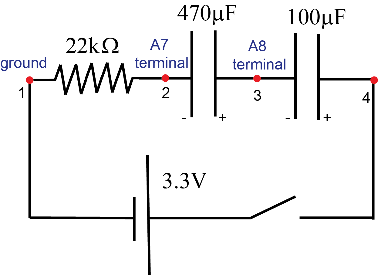
- Build the circuit shown in the diagram in Figure E.6. Please pay attention to the polarity of the capacitors (negative terminals of the capacitors should be at lower potential than positive ones).
- Make sure both capacitors are initially uncharged by short-circuiting them.
- Connect the D6 voltage source in the iOLab device to the point 4 on the diagram. Turn on the voltage. Wait until both capacitors are fully charged (i.e. current through the resistor vanishes).
- Calculate the total charge
 on the combination (integrate the current through the resistor like we did in previous experiments). Show this value in the report.
 - Measure the voltage across each capacitor. The voltage across
 capacitor is measured by A8. The voltage across
  is just the 3.3V less voltage across
  capacitor.
 - Calculate the charge on each capacitor (use accurate values for capacitances from Experiment 1 and voltages you measured in part 5). Are these charges the same? Do they match the total charge on the combination you calculated in part 4? Show your calculations in your report.
- Use the value for the total charge from part 4 and the voltage value across the combination to calculate the equivalent capacitance
 for this combination.
 - Calculate equivalent capacitance for your combination of capacitors in series using expression (I.10) we derived in class and accurate values for capacitances from Experiment 1. Does it match the value you obtained in part 7? Show your calculations in the report.
Experiment 7. Combination of Capacitors.
In this experiment we will measure and theoretically calculate the equivalent capacitance of the combination of 4 capacitors.
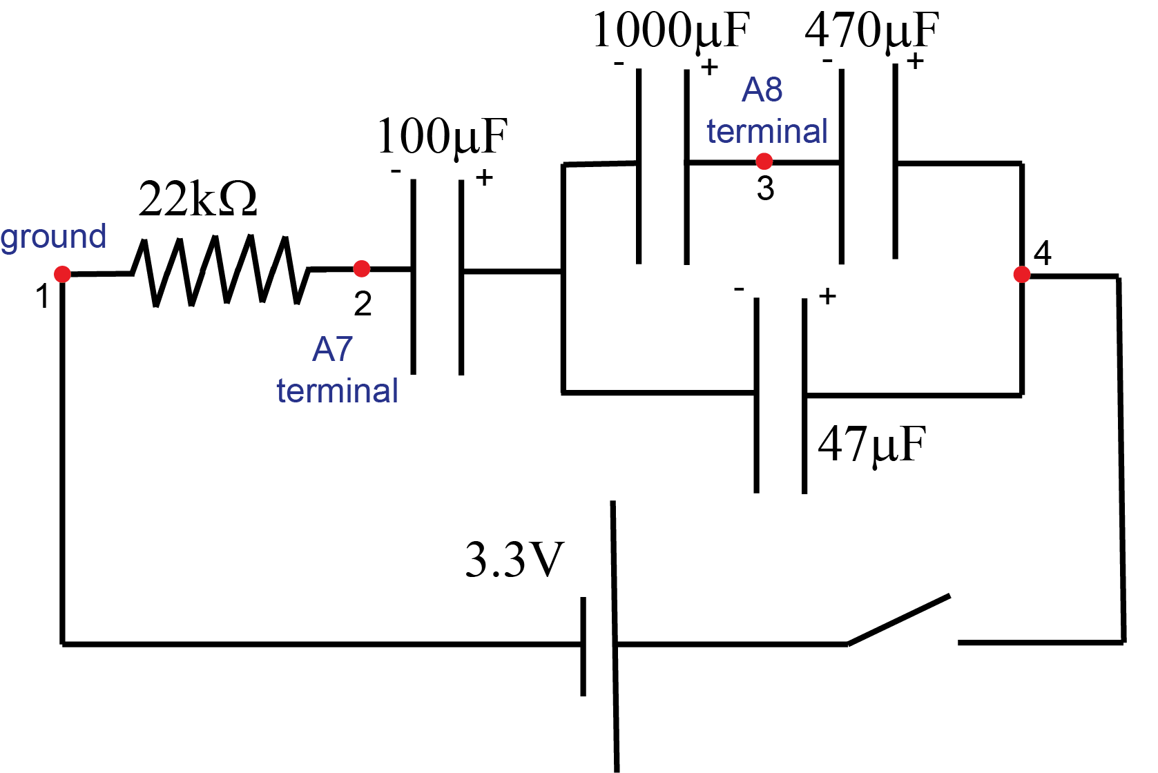
- Build the circuit shown in the diagram in Figure E.7. Pay attention to the polarity of the capacitors.
- Make sure all capacitors are initially uncharged by short-circuiting them.
- Connect the D6 voltage source in the iOLab device to the point 4 on the diagram. Turn on the voltage. Wait until capacitors are fully charged (i.e. current through the resistor vanishes).
- Calculate the total charge
 on the combination (integrate the current through the resistor like we did in previous experiments). Show this value in the report.
 - Use the value for the total charge
 and the voltage across the combination (3.3V) to calculate the equivalent capacitance
  for this combination.
 - Record the voltage at point 3 measured by A8.
- Draw the circuit diagram and solve the circuit (theoretically calculate equivalent capacitance and voltages across each capacitor using accurate values for capacitances from Experiment 1 and the voltage 3.3V across the combination). Include your solution in the report. Does the theoretical value for
 match the one obtained from your measurement? Based on your solution what is the potential (relative to the ground at point 1) at point 3? In your report compare theoretical value for the potential at point 3 with the measured value. Make a snapshot of your breadboard setup for this experiment and include it into report.