When a constant potential difference ![]() is applied to conducting material, such as a wire, a current density
is applied to conducting material, such as a wire, a current density ![]() is established that is directly proportional to the electric field
is established that is directly proportional to the electric field ![]() , created within the material. The constant of proportionality is known as the electric conductivity
, created within the material. The constant of proportionality is known as the electric conductivity ![]() , and the relation is known as Ohm's Law
, and the relation is known as Ohm's Law
|
(I.1) |
which also can be expressed in a more familiar form,
|
(I.2) |
that relates the macroscopic and measurable quantities: the current ![]() and the resistance
and the resistance ![]() of the object. The unit of resistance is Ohms:
of the object. The unit of resistance is Ohms: ![]() .
.
Resistors are ubiquitous in circuits that dissipate electrical energy into thermal energy and are usually constructed from ceramic materials. The power dissipated in the resistor (i.e. the amount of energy converted to heat per unit time) is given by
|
(I.3) |
which (using Ohm’s Law), can also be written as
|
(I.4) |
or
|
(I.5) |
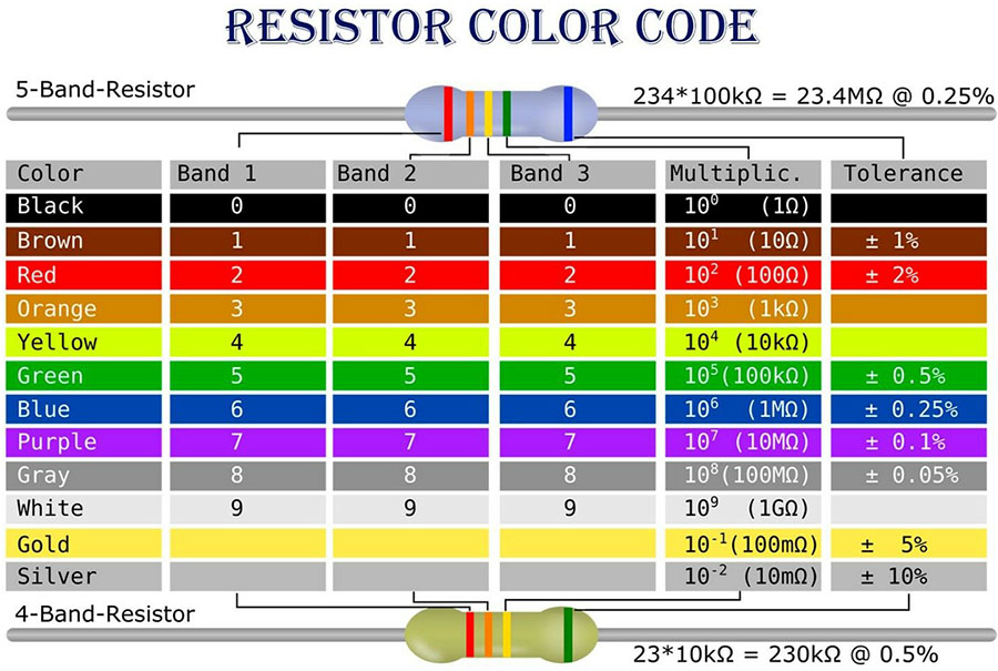
The color code chart in Figure I.1 shows how resistors are labeled by colored bands. In this lab we will be working with resistors labeled with 5 bands. Most likely they will have 1% tolerance.
![]() is connected across the capacitor, equal and opposite charges collect onto the plates. Once the plates are fully charged, one plate will have a net positive charge
is connected across the capacitor, equal and opposite charges collect onto the plates. Once the plates are fully charged, one plate will have a net positive charge ![]() while the other plate will have
while the other plate will have ![]() . The capacitance
. The capacitance ![]() is defined by
is defined by
|
(I.6) |
Capacitance ![]() is a measure of how much charge a capacitor can hold, for a given voltage
is a measure of how much charge a capacitor can hold, for a given voltage ![]() across its plates. Capacitance is a (constant) property of a given capacitor that is defined by its geometry and dielectric material used in building capacitor. Capacitance does not depend on the voltage across the capacitor or the charge stored on the capacitor.
across its plates. Capacitance is a (constant) property of a given capacitor that is defined by its geometry and dielectric material used in building capacitor. Capacitance does not depend on the voltage across the capacitor or the charge stored on the capacitor.
Combination of capacitors can be replaced with the equivalent capacitor. Such a replacement will not affect the rest of the circuit. Some (not all) of the capacitor circuits may be represented as combinations of parallel and/or series connections.
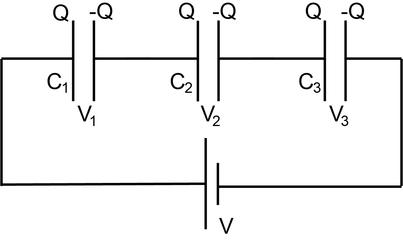
Parallel capacitors (Figure I.2) have the same voltage. The equivalent capacitance of capacitors in parallel is the sum of capacitances:
|
(I.7) |
The charge on the equivalent capacitor is the sum of charges on capacitors:
|
(I.8) |
The voltage on the equivalent capacitor is the same as the voltage on each capacitor:
|
(I.9) |
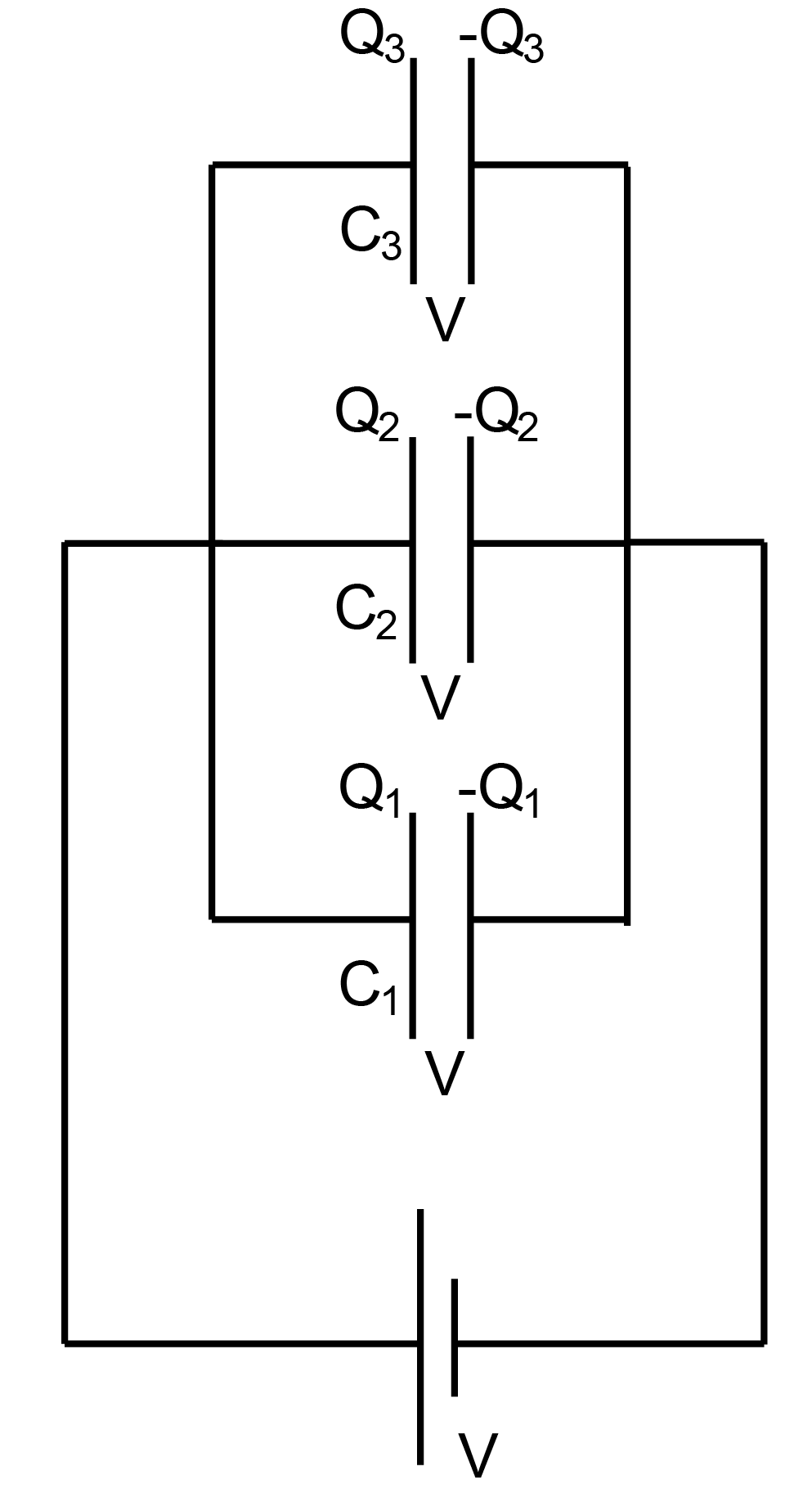
Capacitors connected in series (Figure I.3) have the same charge. The equivalent capacitance of capacitors in series is the inverse of the sum of the inverses of capacitances:
|
(I.10) |
The charge on the equivalent capacitor is the same as the charge on each capacitor:
|
(I.11) |
The voltage on the equivalent capacitor is the sum of voltages on capacitors:
|
(I.12) |
The energy stored in a capacitor can be written in several ways:
|
(I.13) |
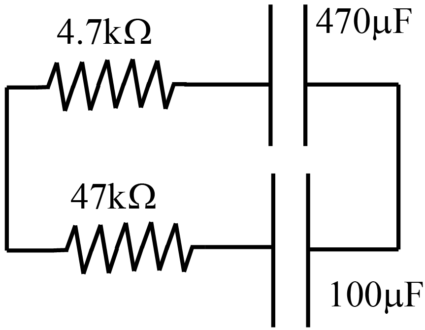
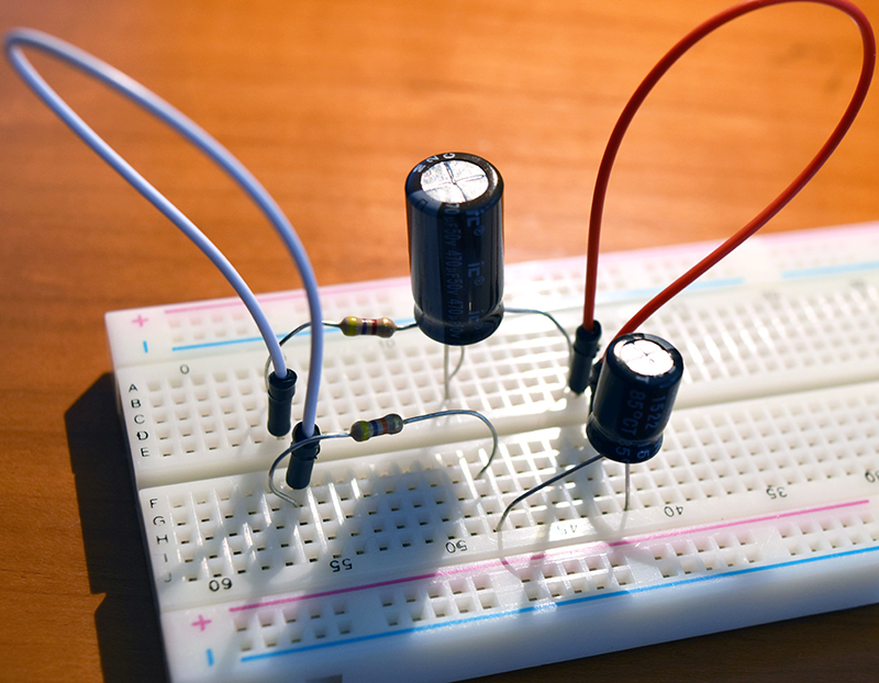
In this lab, you will construct real physical circuits with capacitors and resistors, draw corresponding circuit diagrams and solve them. Then you will verify that your solution agrees with the observed charges and voltages in the real circuit.
Breadboard.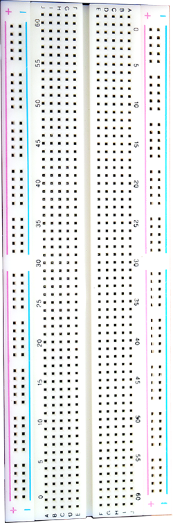
The power rails run vertically down the sides. Your breadboard has two power rails on the left and two power rails on the right. Each pair is labelled as "+" (red) or "−" (blue). You do not have to use these contacts for power. However, experience shows that power and ground are the most common contacts in your final circuit and these rails provide many connected holes. Every hole on the power rail is connected. It is important to know that the pair of rails on the left is not connected to the pair of rails on the right. If you wish to have the same power voltages available on both sides, you will need to add your own jumper wires to accomplish this.
Tips.
- Use the “Analog” iOLab probes to measure the voltage in various places in the circuit to determine the voltage drops across the key components. Note: If the probe is not attached properly, the reading will be very noisy and around 1.5 – 1.6 V.
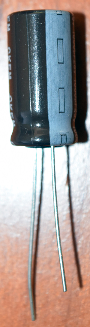
- The provided capacitors are polarized, meaning that they have a positive and negative terminal (see Figure I.7). The negative terminal is the shorter of the two and is also identified by the light strip with “-“ sign. It must be attached to the terminal strip at lower potential (i.e. leading to the ground) than the positive (longer) terminal.
- The resistances and given with 1% tolerance (accuracy).
- The capacitances are given with 20% tolerance (accuracy). This means that the capacitance value written on the capacitor (stated value) gives you only a ballpark idea what the capacitance is. You should not rely on this value in your calculations. Instead you should measure the capacitance yourself (in Experiment 1) and use your accurate data (rather than stated value) in all your calculations.
- Use the “D6" voltage source in the iOLab device. This provides a digital voltage source that can be toggled on/off from the software. To activate it, you need to select Output configuration in the Settings/Expert Mode menu. Then the voltage control will appear in the sidebar.