Challenge 1. Resistance in a cube.
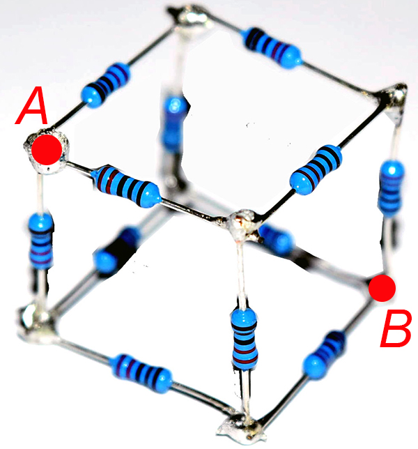
![]() resistor along each edge (see Figure C.1). Follow the procedure of Experiment 9 (resistance between vertices of tetrahedron) to measure AND calculate the equivalent resistance between nodes
resistor along each edge (see Figure C.1). Follow the procedure of Experiment 9 (resistance between vertices of tetrahedron) to measure AND calculate the equivalent resistance between nodes ![]() and
and ![]() that correspond to:
that correspond to:
- diagonally opposite corners of the cube – Figure C.1 (bonus 5%)
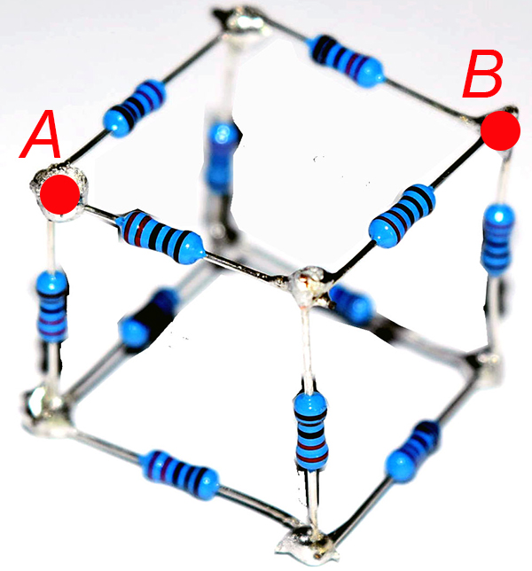
- diagonally opposite corners of a face – Figure C.2 (bonus 10%)
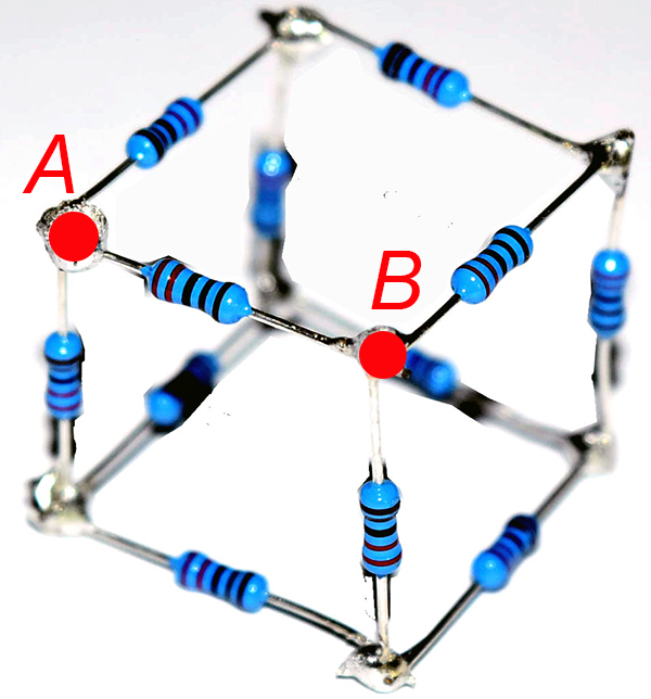
- adjacent corners – Figure C.3 (bonus 5%)
Your report should contain your equivalent diagram for the cube resistance between appropriate nodes and your calculation of its equivalent resistance in terms of the edge resistance. Include the result of your measurement and your comparison between measured and calculated values for the cube with edge resistance of ![]() .
.
Challenge 2. RC Circuit (bonus 10%).
In this experiment we will build and analyze RC circuit.
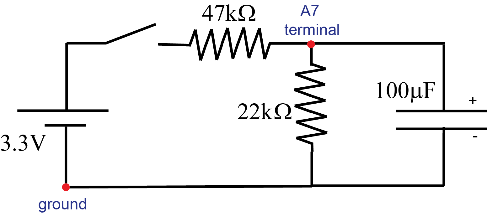
- Build the circuit shown in the diagram (Figure C.4). Pay attention to the polarity of capacitor.
- Make sure that the capacitor is initially uncharged.
- Connect the source (i.e. 3.3V terminal of the iOLab device).
- Record the voltage across the capacitor (A7 terminal) as a function of time as capacitor is being charged.
- Once the voltage across the capacitor becomes constant (capacitor is fully charged) disconnect the voltage source (“open the switch”). Observe the discharge of the capacitor through 22kΩ resistor. Export your measured data into Excel. Make a plot of the voltage across the capacitor as a function of time (restrict the plot to the charging process only).
- Use Kirchhoff’s rules to write loop equations for this circuit and solve them. This will involve solving differential equation – please check class notes – very similar equation was solved in class. Initial condition:
 (initially the capacitor is uncharged therefore your solution will describe charging process. The discharge process is solved in the textbook). Check that your solution provides correct values for the voltage across the capacitor at
  and
and  . What is the time constant for charging process?
 - Use your solution to plot calculated values for the voltage across the capacitor V(t)=Q(t)/C as a function of time on the same graph as your experimental data. Use accurate value for the capacitance of the
 capacitor from Lab 3.
 - Your report should contain your analytic solution for the
 on the capacitor, your time constant for the charging process, and the graph comparing your solution with the measured data for the voltage across the capacitor as a function of time.