When a constant potential difference ![]() is applied to conducting material, such as a wire, a current density
is applied to conducting material, such as a wire, a current density ![]() is established that is directly proportional to the electric field
is established that is directly proportional to the electric field ![]() , created within the material. The constant of proportionality is known as the electric conductivity
, created within the material. The constant of proportionality is known as the electric conductivity ![]() , and the relation is known as Ohm's Law
, and the relation is known as Ohm's Law
|
(I.1) |
which also can be expressed in a more familiar form,
|
(I.2) |

![]() and the resistance
and the resistance ![]() of the object. The unit of resistance is Ohm:
of the object. The unit of resistance is Ohm: ![]() .
.
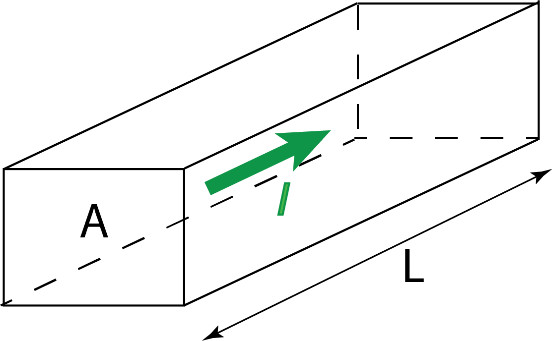
In a regular three-dimensional conductor (Figure I.1), the resistance can be written as
|
(I.3) |
where ![]() is the resistivity of the material,
is the resistivity of the material, ![]() is the cross-sectional area, and
is the cross-sectional area, and ![]() is the length of the conductor.
is the length of the conductor.
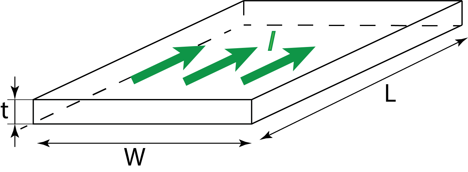
Sheet resistance (two-dimensional systems).
For the thin conducting sheet (Figure I.2) the rectangular cross-sectional area can be represented as a product of the width ![]() and the thickness
and the thickness ![]() . The resistance can be written as:
. The resistance can be written as:
|
(I.4) |

where ![]() is the sheet resistance. Sheet resistance is applicable to two-dimensional systems in which thin films are considered two-dimensional entities. When the term sheet resistance is used, it is implied that the current is along the plane of the sheet, not perpendicular to it. Resistivity
is the sheet resistance. Sheet resistance is applicable to two-dimensional systems in which thin films are considered two-dimensional entities. When the term sheet resistance is used, it is implied that the current is along the plane of the sheet, not perpendicular to it. Resistivity ![]() (also known as bulk resistivity, specific electrical resistivity, or volume resistivity) is in units of
(also known as bulk resistivity, specific electrical resistivity, or volume resistivity) is in units of ![]() . When divided by the sheet thickness (m), the units are
. When divided by the sheet thickness (m), the units are ![]() /m=
/m=![]() . An alternative, common unit is “ohms square” (denoted “Ω ◻”) or “ohms per square” (denoted “Ω/◻”), which is dimensionally equal to an ohm, but is exclusively used for sheet resistance. This is an advantage, because sheet resistance of 1 Ω could be taken out of context and misinterpreted as bulk resistance of 1 ohm, whereas sheet resistance of 1 Ω/◻ cannot thus be misinterpreted. The reason for the name "ohms per square" is that a square sheet with sheet resistance 10 ohm/square has an actual resistance of 10 ohm, regardless of the size of the square. (For a square,
. An alternative, common unit is “ohms square” (denoted “Ω ◻”) or “ohms per square” (denoted “Ω/◻”), which is dimensionally equal to an ohm, but is exclusively used for sheet resistance. This is an advantage, because sheet resistance of 1 Ω could be taken out of context and misinterpreted as bulk resistance of 1 ohm, whereas sheet resistance of 1 Ω/◻ cannot thus be misinterpreted. The reason for the name "ohms per square" is that a square sheet with sheet resistance 10 ohm/square has an actual resistance of 10 ohm, regardless of the size of the square. (For a square,![]() , so
, so ![]() ).
).
Since current density is ![]() and the conductivity is
and the conductivity is ![]() we can write Ohm’s Law for a sheet as:
we can write Ohm’s Law for a sheet as:
|
(I.5) |
At a point on the sheet where electric field is ![]() the current through a small segment
the current through a small segment ![]() perpendicular to
perpendicular to ![]() is:
is:
|
(I.6) |
Resistors are ubiquitous in circuits that dissipate electrical energy into thermal energy and are usually constructed from ceramic materials. The power dissipated in the resistor (i.e. the amount of energy converted to heat per unit time) is given by
|
(I.7) |
which (using Ohm’s Law), can also be written as
|
(I.8) |
or
|
(I.9) |
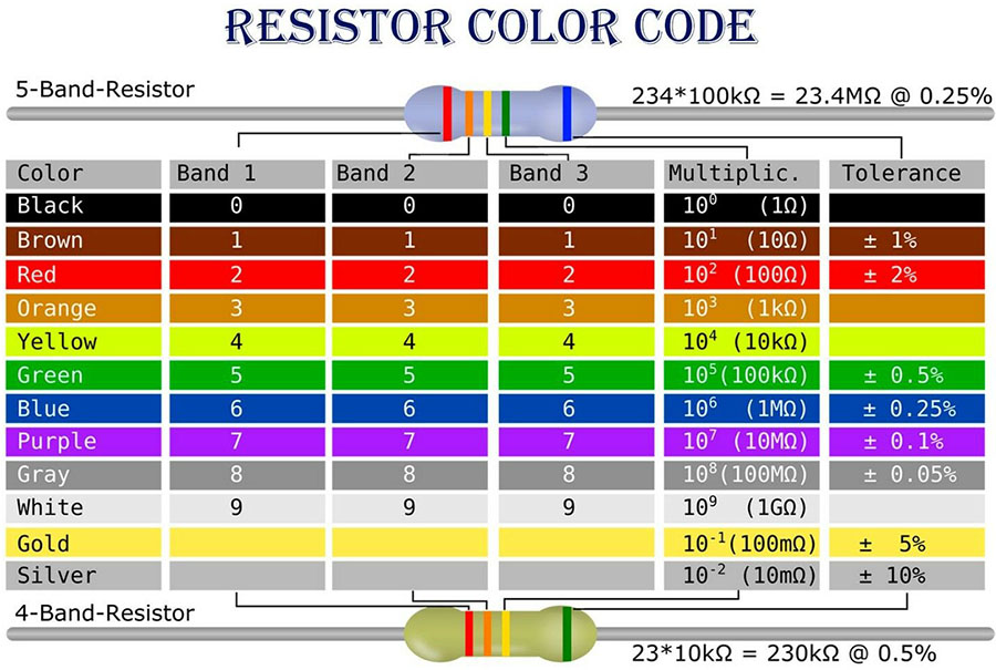
The color code chart in Figure I.3 shows how resistors are labeled by colored bands. In this lab we will be working with resistors labeled with 5 bands. Most likely they will have 1% tolerance.


Parallel resistors (Figure I.4) have the same voltage. The equivalent resistance of resistors in parallel is the inverse of the sum of the inverses of resistances:
|
(I.10) |
The current through the equivalent resistance is the sum of currents through resistors:
|
(I.11) |
The voltage across the equivalent resistance is the same as the voltage across each resistor:
|
(I.12) |
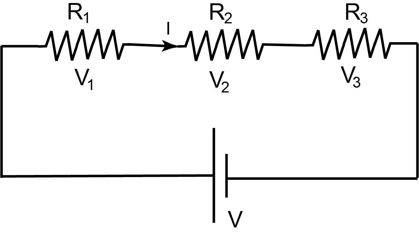
Series resistors (Figure I.5) have the same current. The equivalent resistance of resistors in series is the sum of the resistances:

|
(I.13) |
The current through the equivalent resistance is the same as the current through each resistor:
|
(I.14) |
The voltage across the equivalent resistance is the sum of voltages across resistors:
|
(I.15) |
Kirchhoff’s rules.
- The current through each element must equal the voltage across that element divided by the resistance of the element.
- The algebraic sum of the currents into the node must be zero (i.e. the sum of the currents coming into the node equals to the sum of the currents leaving the node). This rule follows from the charge conservation.
- The sum of the potential differences taken in order around a loop of the network, a path beginning and ending at the same node, is zero.
RC Circuits are circuits that have resistors and capacitors. In general, currents and voltages in such circuits are time-dependent and can be found by applying Kirchhoff’s rules to the loops in the circuit and solving resulting differential equations.
There are special cases where RC circuits can be solved with less effort. Let’s assume initially all capacitors in the circuit are not charged and the switch connecting the circuit to the voltage source is closed at time t=0. Since capacitors and not charged voltages across them are all zero and therefore capacitors may be replaced (just at time t=0) with short-circuit wires. The resulting circuit contains only resistors and can be solved (relatively) easily to find initial currents and voltages at time t=0.
Now assume the switch has been closed for a long time (![]() . All capacitors are fully changed and all currents in the circuit are steady (do not vary with time). There is no additional charge delivered to capacitors – therefore there are no currents to/from capacitors. We may replace capacitors with “breaks in the circuit”. The resulting circuit contains only resistors and can be solved (relatively) easily to find steady currents and voltages long time after the switch has been closed (
. All capacitors are fully changed and all currents in the circuit are steady (do not vary with time). There is no additional charge delivered to capacitors – therefore there are no currents to/from capacitors. We may replace capacitors with “breaks in the circuit”. The resulting circuit contains only resistors and can be solved (relatively) easily to find steady currents and voltages long time after the switch has been closed (![]() .
.