Lab 6.
Electromagnetic Induction.
Introduction.
Faraday discovered that a wire with a changing current can induce a current in a nearby wire. He determined that any change in magnetic flux through the loop induces emf in it:
(I.1) |
The emf and associated current is generated through an electric field inside the wire that is described by the last equality in the equation above, where C is the curve that bounds the surface S. The differential form of Faraday's Law is given by
(I.2) |
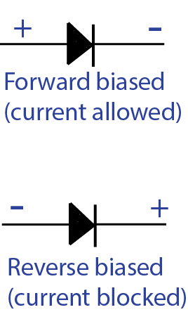
Faraday's Law gives the amplitude of the emf, but Lenz's Law gives the direction of the induced current. It states that the induced current creates an induced magnetic field that opposes the change in magnetic flux.
If we have two circuits C1 and C2, a current ![]() in circuit C1 will produce a flux
in circuit C1 will produce a flux ![]() through the other circuit. The mutual inductance
through the other circuit. The mutual inductance ![]() is defined by
is defined by
(I.3) |
It then follows that changing ![]() produces an emf in C2 equal to
produces an emf in C2 equal to
(I.4) |
Similarly, a current ![]() in circuit C2 will produce a flux
in circuit C2 will produce a flux ![]() through the circuit C1. The mutual inductance
through the circuit C1. The mutual inductance ![]() is defined by
is defined by
(I.5) |
The two coefficients of mutual inductance are symmetric:
(I.6) |
A current I in a circuit will produce a flux ![]() through the circuit. The self-inductance of this circuit is defined by
through the circuit. The self-inductance of this circuit is defined by ![]() . The emf induced in this circuit is then
. The emf induced in this circuit is then
(I.7) |
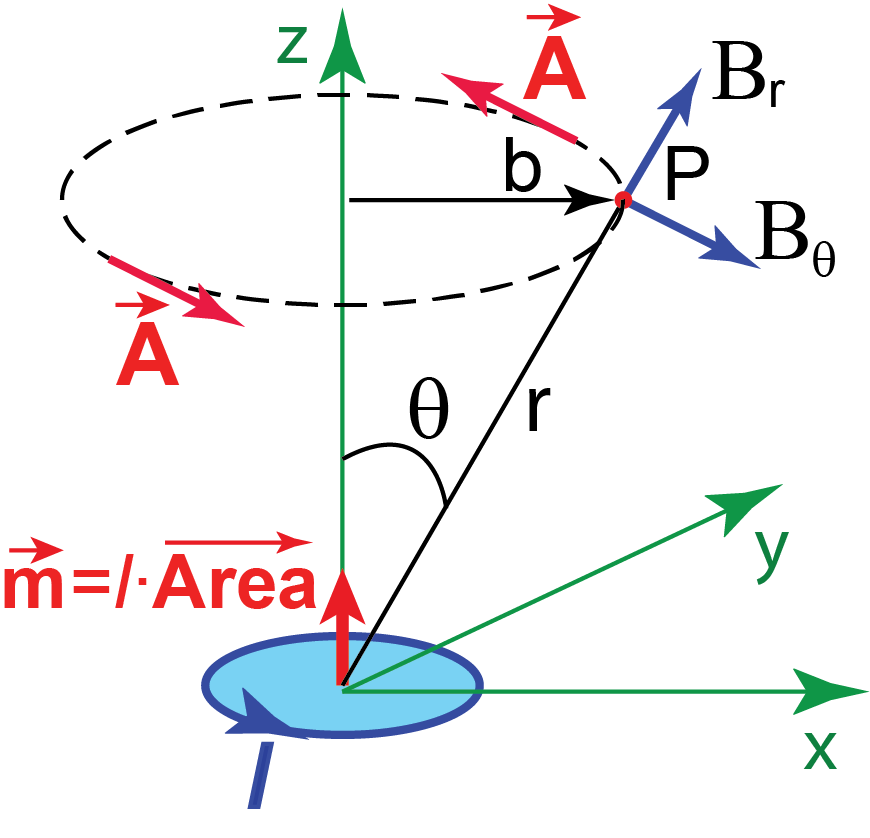
Magnetic dipole moment ![]() of the current loop is a vector, its direction is that of the directed area of the region surrounded by the loop:
of the current loop is a vector, its direction is that of the directed area of the region surrounded by the loop:
![]()
Far field of the magnetic dipole ![]() in polar coordinates is (see Figure I.1):
in polar coordinates is (see Figure I.1):
![]() ,
, ![]() ,
, ![]() (I.8)
(I.8)
In Cartesian coordinates (assuming setup in Figure I.1) this magnetic field is:
![]() ,
, ![]() ,
, ![]() (I.9)
(I.9)
Vector potential of the magnetic dipole ![]() located on the z axis is tangent to the horizontal circle with the center on z axis. Its magnitude is:
located on the z axis is tangent to the horizontal circle with the center on z axis. Its magnitude is:
(I.10) |
Since ![]() using Stokes’ theorem we obtain the flux of the magnetic field of the magnetic dipole through the circle of radius b with the center on z axis (see Figure I.1):
using Stokes’ theorem we obtain the flux of the magnetic field of the magnetic dipole through the circle of radius b with the center on z axis (see Figure I.1):
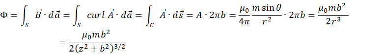 |
(I.11) |